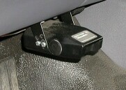
controller mounted
under dashboard
under dashboard

|
controller mounted
under dashboard |
|
Oscilloscope View of
Controller's Output at Various Angles 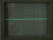
zero degs. / zero volts
|

15 degs. / 2.9 volts
|

20 degs. / 6.3 volts
|

35 degs. / 12.1 volts
scope limitation does not show voltage going to zero |
|
Measuring Pulse Width Modulation 'Voltage' with a Digital Voltmeter
While conducting these experiments I determined that it is possible to use a digital voltmeter to measure pulse width integral voltage. Initially I was unsure that I could do this, because the digital voltmeter repeatedly samples the circuit and then interprets the result in the display. I could imagine a hit-and-miss situation as the digital volt meter sampled the pulse when it was either zero or maximum; resulting in readings that flick from 0 to about 12 volts - or maybe something else in between. But this did not happen, at least with the 3,100 Hertz frequency of the Voyager. I checked the digital voltmeter�s readings with various pulse proportions seen on the oscilloscope, and they seemed to match. I made similar measurements with another digital voltmeter and with an analog voltmeter; they were all in agreement. With this background I felt confident in using a digital voltmeter to take voltage measurements for this project. |
|
Test Rig for Tilting the Voyager and Making Voltage and Temperature Measurements 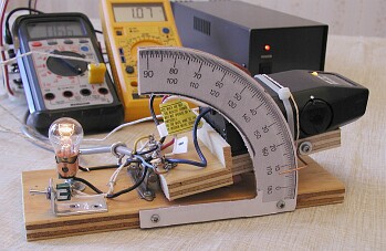
test rig, front view
meter on left measures temperature meter on right, output voltage box at rear is power supply |

test rig, back view
temperature probe is under polyester wad |
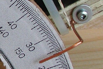
test rig, angle pointer
|
|
Output Voltage Measurements at Various Angles and/or Temperatures GRAPH 1 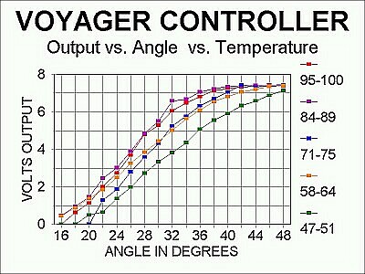
output voltage at various angles for
five temperature ranges (see text) gain and level controls each set to one-half |
GRAPH 2
output voltage for temperature
range of 48 to 99 degrees gain set at one-half level control set at neutral (see text) |
|
Temp. F. 47-51 58-64 71-75 84-89 95-100 |
Voltage 3.83 5.01 5.25 6.58* 6.06* *see text |